CLEAN COAL (Part 3)
I hadn’t planned on a part 3 for clean coal, because I thought that once I had shown how something so technical was reduced to an off the cuff comment so that it could be used to say that something like this was actually within reach, then nothing more would need to be added.
However, something nagged away at me, thinking that I might have missed something, you know, when your brain works on something independent of what you’re actually doing, and then prompts you when it finds the solution.
I was thinking of including an image with the post but decided not to, as the explanation of the theory seemed to me to suffice.
The irony was that after posting, our friend at PA Pundits emailed me and wondered why I hadn’t included an image.
I revisited the only image I did have and noted that it was only average. I’ve learned in my travels around the Internet that if you can’t find what you want, then just change the wording of the entry in the search engine.
I did this and found some better images. One of them was one I had seen prior to the last post and dismissed it. Today I noticed it again, and was just about to dismiss it again as unsuitable when something told me to wait. I looked at the image and just could not figure out why it nagged away at me. On the off chance I just saved the image, and went somewhere else. I found another couple of simple diagrams that I will include with some text in explanation.
As I was actually working on that text, blink, I ‘got a message’ to go and look at that image that was nagging away at me. When I looked closely again, it came to me like a ‘Eureka’ moment.
I’ll get to that a little further on, but the images I did find are these, and why I’m actually including them at all, is they only accentuate what I was actually saying in the previous post. The ‘dumbing down’ of something that is by its very nature highly technical. The ‘talking heads’ that so calmly say the simple one liners actually make it sound like it can be done, when in fact, the process is so complex that it probably might not go any further than the theory.
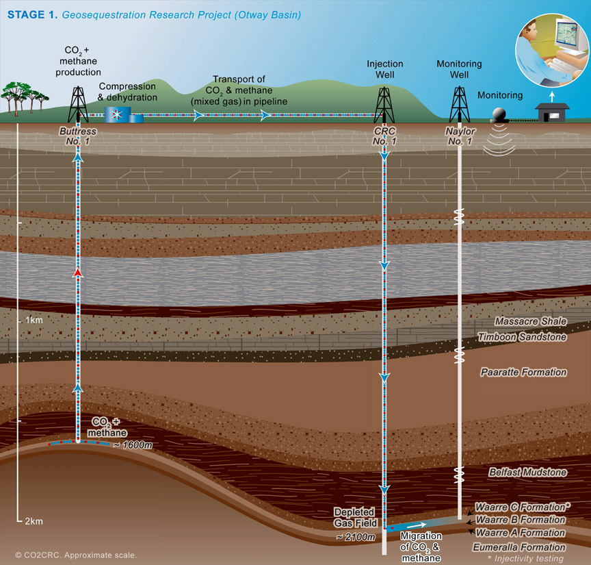 |
| This image from CO2CRC Australia. Click on the image to open in a larger window. |
This first shows a diagram for the geosequestration process. This is a proposal for a pilot plan in the Otway Basin oil and gas reserves off the coast of Southern Australia at the border between the States of Victoria and South Australia with Tasmania to the South, and in Bass Strait.
This project is one that draws existing the gas from the field, then compresses it, piping it then to the injection well within the same field.
The term geosequestration is mostly used in Australia, and is not used often, because the thinking is why say something of a technical nature when it can be explained away with the term ‘clean coal’, something that everybody understands. Yeah! Right!
You will probably hear variations on the same theme as a suitable acronym is sought, as they seem to do with everything these days, so you’ll probably hear the most popular one, that of CCS. (Carbon Capture and Storage, or the more difficult Carbon Capture and Sequestration)
See how the diagram is just so basic. It shows where the carbon is captured, then separated, then compressed and then injected back into the ground. Simple isn’t it? Leave the science to people who know the science. Can you see now how impressionable environmentalists look at something like this and then ask why it can’t be done.
 |
| Image from CO2CRC Australia. click on the image to open in a larger window. |
This second image again shows a simple diagram and how it could be used to effectively explain something so complex. With this diagram, a power plant is shown as the source of the CO2. The next two stages should realistically be at the same site as the plant but for simplicity sake, they have been separated, thereby giving a false impression of the ease with which something as complex as this can be accomplished. The injection phase gives the impression that you just drill a hole, seemingly anywhere, and just stuff it down there. A simple diagram like this could be mounted on an easel, and with the help of a pointer, even a politician would look good explaining the absolute simplicity of the capture and storage of those harmful greenhouse gases. The coal miners are happy because their interests are looked after, and politicians, without trying to look too desperate, have protected the immense royalty payments flowing to their State. Seeing something like this, scientists and engineers must shake their heads with horror. A diagram like this leaves out more than it attempts to include, and is an eloquent example of misrepresentation.
Hydrogen Powered Electricity Generation.
 |
| The Hydrogen Power Plant at Carson California. Image from BP Alternative Energy. Click on the image to open in a larger window. |
The BP Carson Hydrogen Power Project
When first looking at this diagram, I noticed what I thought as the burning of coal, or in this case petroleum coke, to produce power, the basic diagram separating the CO2, and the transporting of the CO2 back into the ground, just another simplified diagram. However, the thing about it is this.
True, it is being burned, and a turbine drives a generator to produce the power. However, and here’s the really clever part. Because I was thinking that the CO2 removal part is at the far end of the process, I looked with interest at the image and then just went somewhere else.
When I was prompted to look again. I found something I had missed up front, but when triggered to look more closely, I noticed that the something I missed was in actual fact my brain expecting to see something, hence misinterpreting what I was actually seeing.
Now intrigued, I looked a little more closely at the image, and then read the article.
The petroleum coke is burned and electricity is produced and there the similarity ends.
Previously, coal is burned to boil water to steam, which drives the turbine which drives the generator. The burnt coal produces ash and smoke. The smoke is captured and the CO2 separated from it, and that process continues.
With this process however, the petroleum coke is burned and water is introduced. Through a chemical reaction, two gases are produced, CO2 and Hydrogen. The CO2 is then sent on its way and the hydrogen is used to drive a modified gas turbine which in turn drives the generator. As similar as the process sounds, it is entirely different. The CO2 is removed earlier in the process, and as much as you think it is the same, this is actually different. The CO2 being removed earlier in the process and in this manner is at a level of 90%, so on average, less than 10% of the CO2 produced is then emitted into the atmosphere. The remaining CO2 is then transported via pipeline and used in the enhanced recovery of oil, where the CO2 is pumped down into existing oilfields to force more oil to where it is being pumped from the ground, extending the life of those oilfields, and saving money involved in drilling into that same field in another place.
The hydrogen part of the process is used to drive a modified dual cycle turbine.
This process is currently under construction by BP at the site of their refinery at Carson, south of Los Angeles, and the power plant will produce 500MW of power mostly for peak power purposes, and not for baseload power. I understand that the diagram still makes the process look simple and leaves more unsaid than it actually does tell us, but it is an encouraging move forward.
The same Company also had a similar plant in the planning process for Scotland. It was going to use Natural Gas from the vast North Sea fields for the front end of the process, the conversion to Hydrogen. The CO2 was then going to be routed back to the North Sea oilfields and used in the recovery of oil. This was mooted to extend the life of those oilfields by a further 30 years. Evidently the Scottish parliament was not all that keen on being a joint venture partner and supplying some of the money for the project, and BP pulled out of the deal.
This plant at Carson uses Petcoke, which is petroleum coke. This is what is left after the oil refining process the thick black tar like substance at the finish of the process, used also in the power generation process, but in this case burnt to extract the Hydrogen and the CO2. The refinery on the same site produces around 4000 tons of petcoke each day, so the proximity of the fuel for the plant produces savings in transport of the fuel itself.
What you see here is a series of diagrams that make the process look simple, and this is what is being used to distract people into believing that the process is a simple one.
It has been said by some scientists and engineers that this could be a tens to hundreds of billion dollars wild goose chase that will only end up in abandonment with no suitable solution, other than fiddling around at the edges, all in a desperate attempt to look after the royalties from coal.
KPPSTony


TonyfromOz
Wed 07/30/2008
Thanks Unnikuttan for that comment.
I started to reply, but the reply might have been long, so rather than reply here, I contributed a new Post. The reply in answer is just not as simple as the comment you make, but what your comment does highlight is to show that we are being blinded into believing just what those pushing the whole argument want us to believe. There is much more below the surface that we need to be told so we are appraised of the full story, the implications, and exactly what needs to be done, and just what the cost might be, both on a monetary level, and at the personal level.
The blind reasoning that Kyoto is good for the environment puts it into the category of “Well, how can this not be good then.”
The real implications remain hidden because if those were put out into the public domain, then people might just say, “Hey! Wait a minute.”
I hope you’ll go to the new post for a comprehensive reply. The following is the link to that post.
Tony.
LikeLike
unnikuttan
Wed 06/04/2008
I hope that Kyoto will not fail.
LikeLike